|
Model
|
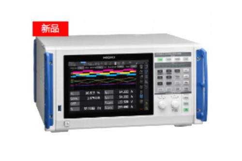
PW8001+U7005
|
PW8001+U7001
|
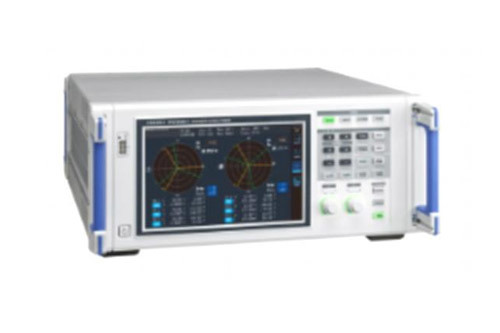
PW6001
|
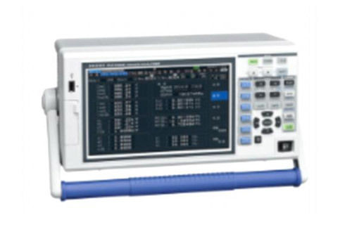
PW3390
|
|
Use
|
SiC,GaN Measurement Of Inverters, Reactors, And Transformer Losses
|
High Efficiency Igbt Inverter,
High Efficiency Measurement Of Pv Inverters |
Measurement Of High-Efficiency Igbt Inverters
|
It Combines High Accuracy And Maneuverability
|
|
Measurement
|
Measure The Frequency Bandwidth
|
DC,0.1Hz~5 MHz
|
DC,0.1Hz~1MHz
|
DC,0.1 Hz~2MHz
|
DC,0.5Hz~200 kHz
|
|
50 Hz/60 Hz Basic Accuracy Of Power
|
±(0.01% of reading+0.02% of range)
|
±(0.02% of reading+0.05% of range)
|
±(0.02% of reading+0.03% of range)
|
±(0.04% of reading+0.05% of range)
|
|
DC Basic Accuracy Of Power
|
±(0.02% of reading+0.03% of range)
|
±(0.02% of reading+0.05%of range)
|
±(0.02% of reading+0.05%of range)
|
±(0.05% of reading+0.07%of range)
|
|
10 kHz Basic Accuracy Of Power
|
±(0.05% of reading+0.05% of range)
|
±(0.2% of reading+0.05% of range)
|
±(0.15% of reading+0.1%of range)
|
±(0.2% of reading+0.1%of range)
|
|
50 kHz Basic Accuracy Of Power
|
土(0.15% of reading+0.05% of range)
|
±(0.4%of reading+0.1% of range)
|
土(0.15% of reading+0.1%of range)
|
土(0.4% of reading+0.3%of range)
|
|
Number Of Power Measurement Channels
|
1 ch/2 ch/3 ch/4 ch/5 ch/6 ch/7 ch/8 ch
U7001 Or U7005 Must Be Specified When Ordering (Can Also Be Used At The Same Time)
|
1 ch/2 ch/3 ch/4ch/5 ch/6 ch
This Must Be Specified At The Time Of Ordering
|
4 ch
|
|
Voltage And Current Adc Sampling Function
|
18-bit,15 MHz
|
16-bit,2.5 MHz
|
18-bit,5 MHz
|
16-bit,500 kHz
|
|
Voltage Range
|
6V/15V/30 V/60 V/150 V/300 V/600 V/1500V
|
6 V/15V/30 V/60 V/150 V/300 V/600V/1500V
|
15 V/30 V/6OV/150 V300 V/600 V/1500V
|
|
Voltage Range
|
100 mA~2000 A(6 Ranges, Depending On The Sensor)
|
probe1:100 mA~2000 A(6 Ranges, Depending On The Sensor)
probe2:100mV/200mV/500mV/1 V/2V/5V
|
probe1:100 mA~2000 A(6 Ranges, Depending On The Sensor)
probe2:100mV/200 mV/500 mV/1 V/2 V5V
|
100 mA~8000 A(6 Ranges, Depending On The Sensor)
|
|
Common-Mode Rejection Ratio(CMRR)
|
50 Hz/60 Hz:120 dB以上
100 kHz:110 dB Above
|
50 Hz/60 Hz:100 dB Above
100 kHz:80 dB typical
|
50 Hz/60 Hz:100 dB Above
100 kHz:80 dB Above
|
50 Hz/60 Hz:80 dB Above
|
|
Temperature Coefficient
|
0.01%/℃
|
0.01%/℃
|
0.01%/℃
|
|
Voltage Input Method
|
Optically Insulated Input, Resistor Voltage Divider
|
Isolated Input, Resistor Voltage Divider
|
Optically Insulated Input, Resistor Voltage Divider
|
Isolated Input, Resistor Voltage Divider
|
|
Current Input Method
|
Isolated Input Via Current Sensor
|
Isolated Input Via Current Sensor
|
Isolated Input Via Current Sensor |
|
External Current Sensor Input
|
O(ME15W)
|
O(ME15W,BNC)
|
O(ME15W,BNC)
|
O(ME15W)
|
|
Power Supply For External Current Sensors
|
O
|
O
|
O
|
|
Data Update Rate
|
1 ms/50 ms/200 ms
|
10 ms/50 ms/200 ms
|
50 ms
|
|
Voltage Input
|
Maximum Input Voltage
|
1000V,±2000 Vpeak
|
AC 1000V,DC1500V,±2000 V peak
|
1000 V,±2000 V peak(10 ms)
|
1500V,±2000 V peak
|
|
Maximum Input Voltage To Ground
|
600 V CATIⅢ
1000V CATII
|
AC 600 V/DC 1000V CAT IⅢ
AC 1000 V/DC 1500V CATII
|
600V CATⅢ
1000 VCAT II
|
600 V CATIⅢ
1000V CATII
|
|
Analyse
|
Number Of Channels For Motor Analysis
|
●Up To 4 Motors
|
●Up To 2 Motors
|
●1 Motor
|
|
Motor Analysis Input Form
|
Analog Dc/Frequency/Pulse
|
Analog Dc/Frequency/Pulse
|
Analog Dc/Frequency/Pulse
|
|
Function
|
Current Sensor Phase Compensation Calculations
|
O(Auto)
|
O
|
O
|
|
Harmonic Measurements
|
O(8 Systems Run Independently)
|
O(6 Systems Operating Independently)
|
O
|
|
The Maximum Number Of Harmonic Analyses
|
500 Second-rate
|
100 Second-rate
|
100 Second-rate
|
|
Harmonic Synchronization Frequency Range
|
0.1 Hz~1.5MHz
|
0.1 Hz~1MHz
|
0.1 Hz~300 kHz
|
0.5 Hz~5kHz
|
|
IEC Harmonic Measurements
|
O"
|
O
|
|
|
IEC Flicker Measurement
|
O"
|
|
|
|
FFT spectrum analysis
|
O(DC~4 MHz)
|
O"(DC~1MHz)
|
O(DC~2MHz)
|
O(DC~200 kHz)
|
|
User-Defined Calculations
|
O
|
O
|
|
|
Delta Conversion
|
O(△-Y,Y-△)
|
O(△-Y,Y-△)
|
O(L-Y)
|
|
D/A Output
|
●20 Channels (Waveform Output, Analog Output)
|
●20 Channels (Waveform Output, Analog Output)
|
●16 Channels (Waveform Output, Analog Output)
|
|
Display
|
Display
|
10.1-Inch Tft Color Lcd Display
|
9-inch TFT color LCD display
|
9-inch TFT color LCD display
|
|
Touch Screen
|
O
|
O
|
|
|
Interface
|
External Storage Media
|
Flash Drive(3.0)
|
Flash Drive(2.0)
|
Flash Drive(2.0),CF card
|
|
LAN
(100BASE-TX,1000BASE-T)
|
O
|
O
|
O(仅10BASE-T,100BASE-TX)
|
|
GP-IB
|
O
|
O
|
|
|
RS-232C
|
O(Utmost 115,200 bps)
|
O(Utmost 230,400 bps)
|
O(Utmost 38,400 bps)
|
|
External Controls
|
O
|
O
|
O
|
|
Synchronization Of Multiple Units
|
O(Up to 4 units)
|
|
O(Up to 8 units)
|
|
Optical Port
|
●
|
O
|
|
|
CAN-CAN FD
|
●
|
|
|
|
Size & Weight (W×H×D)
|
About 430 mm×221 mm×361 mm,About 14kg
|
About 430 mm×177 mm×450 mm,About 14 kg
|
About 340 mm×170 mm×156 mm, About4.6kg
|


.jpg")